
- PV Products
PV balance of system
Combiner, meter and grid-connection boxes. 130 GW+ of PV products supplied.
All PV products - Energy Storage
261 Series Standard and PV-storage-diesel versions
418 Series DC-side and all-in-one versions
PulsarWatt Micro Grid AIO Container 20 ft · 90 kWp PV + 261 kWh
STS Cabinet 250 kW / 500 kW · On/off-grid transfer
- Grid-Connection Cabinet Grid tie for storage To be updated
AC Combiner (Paralleling) Cabinet Two 261 cabinets, one grid tie
More storage products Container & Air-Cooled Telecom Base Station Residential & Portable Elevator Energy Saving CFOS Platform - Markets & Solutions
- Projects
- Resources
- News & Insights


250 kW STS Cabinet
Product details
Ties one or two storage cabinets to the grid and the loads: a built-in STS-250KS transfers to off-grid in under 10 ms, and a 150 kVA isolation transformer with pre-charge serves the storage side, all in an IP55 outdoor cabinet.
Where it fits
On-grid, loads and total battery charging share 250 kW: charging one cabinet at 125 kW leaves 125 kW for loads, and slower charging allows more load power. The same shared budget applies with two cabinets. Off-grid capacity depends on the storage, the PCS and the isolation path.
Key features
- One or two storage cabinets Connects one or two storage cabinets; on-grid, loads and battery charging share the 250 kW grid-side budget.
- Fast grid transfer The built-in STS-250KS switches from on-grid to off-grid in under 10 ms.
- Electrical isolation and pre-charge A 150 kVA isolation transformer with integrated pre-charge serves the storage side; the grid-side path bypasses it.
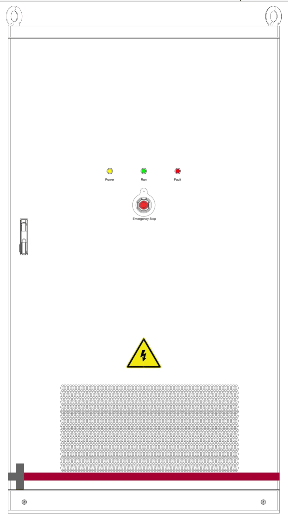
- IP55 outdoor cabinet Circuit protection, export metering, emergency stop and status indicators in one outdoor cabinet.
| AC Connection | |
|---|---|
| Cabinet rated voltage | 400 V AC |
| Storage cabinets connected | One or two |
| STS grid-side rated power | 250 kW |
| STS grid-side rated current | 380 A AC |
| Charging power per cabinet | ≤ 125 kW |
| Load power allocation | Adjusted with total charging power |
| Automatic Transfer with STS | |
|---|---|
| STS model | STS-250KS |
| On-grid to off-grid transfer | < 10 ms |
| STS voltage / tolerance | 380 / 400 V AC, ±15% |
| STS rated frequency | 50 / 60 Hz, ±5 Hz |
| STS communication | RS485 / CAN / Ethernet |
| Enclosure and Installation | |
|---|---|
| Dimensions (W × D × H) | 1,200 × 1,350 × 2,150 mm |
| Cabinet weight | 1,100 ± 10 kg |
| Cabinet ingress protection | IP55 |
| Location / operating altitude | Outdoor, ≤ 2,000 m |
| Cable entry / exit | Bottom entry and exit |
| Integrated Isolation Transformer | |
|---|---|
| Rated capacity | 150 kVA (manual configuration) |
| Rated input / output voltage | 400 / 400 V |
| Phases / vector group | Three-phase, Dyn11 |
| Conductor / insulation class | Aluminum, Class H |
| Transformer efficiency | ≥ 97% |
| Cooling / ambient temperature | AN, -20 to +50 °C |
| Transformer pre-charge | Integrated |
| Protection and Auxiliary Equipment | |
|---|---|
| Grid main breaker QF1 | 400 V AC / 500 A, shunt trip |
| Circuit breaker QF2 | 400 V AC / 315 A, motor operation and shunt trip |
| Load / storage breakers QF3 / QF4 | 400 V AC / 315 A each |
| Surge protective device | DXH06-FCS-4R40 |
| Export metering / CT ratio | YDS60-80, 500 A / 5 A |
| Auxiliary / backup supply | AC 220 V / DC 24 V, 240 W; 24 V backup battery |
| Emergency stop / indication | Emergency stop; power, run and fault indicators |
Specifications from the CFGE Two-Input Grid Transfer Cabinet data sheet. Allow for losses and auxiliary consumption within branch ratings; the final configuration is confirmed per project.
The English / Chinese datasheet downloads directly as PDF. No registration needed.
For other configurations, contact our sales team or write to info@cf-ge.com.
User manuals
User manuals are provided by our sales team with your project.
Quotation & datasheet
Get the matching datasheet and a quote.
Tell us the configuration and market version you need. Sales sends the datasheet for that exact model and a quotation.
- info@cf-ge.com
- +86 173 0062 9666
- Building 13-2, No. 58 Yangguang Avenue, Changshu, Suzhou, Jiangsu, China

PV balance-of-system equipment and energy storage systems, designed and built in Changshu, Suzhou since 2007.